As a part of our creating documentation effort in the UWSim wiki, we have created a developer tutorial about how to create your own device. Long ago we included the Device manager that helps creating different kind of devices in UWSim but we had no time to write about how to use it. We hope this tutorial encourages the development of new simulated sensors and makes UWSim more useful for everyone.
The tutorial still misses some parts, such as interacting with the physics engine, but it is complete in the terms of creating a device and publishing to ROS. If you get lost trying to follow it please let us know so we can improve it!.
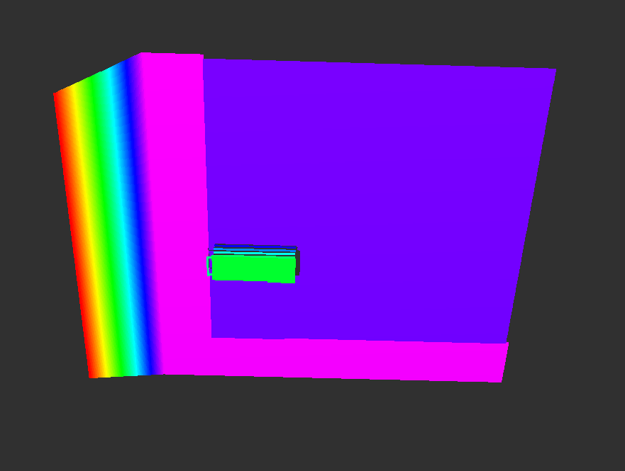
We have recently added a new interface for virtual range image sensors that publishes the result in a pointcloud. So the result is a pointcloud with distances from the camera frame to the nearest obstacle for each point. It is similar to a kinect sensor but take into account kinect sensors do not work underwater!. The sensor has perfect output and even underwater particles have been disabled for it because they produced a strange cloud of noise at a fixed distance. We hope to add an appropriate pattern of noise in the future.
In order to use it just add an interface linked to the virtual range image sensor like this in your rosinterfaces XML section:
As UWSim is being used for different purposes we were in the need of using several scenes and share them. This process was quite tedious, so we have decided to create a basic scene installer that helps with the process of downloading and copying 3D models and configuration scenes in the correct places to be able to run them. This script is already available in the indigo branch in github and can be download here. Just place it in a scenes folder (any with a UWSimScene.dtd file), in the github is already placed in data/scenes, and run it like this:
./installScene -s dredging.uws
You will see some downloads and when it finishes you should have the new scene in your installation, just run uwsim "rosrun uwsim uwsim --configfile dredging.xml" and if everything worked as it should UWSim will start with the new scene (you may need to execute catkin_make install). You can check the available scenes in the new scenes tab of the website and more details on how to use it in the wiki. Finally if you want to share your scenes you can do it here.
Today we are happy to announce UWSim version 1.4 is available in deb packages (and github) for ROS indigo and jade distributions. We have already announced most of the new features of this version as they came, but here is a list in the case you missed something:
Besides this main updates, many bugs fixes and small enhancements have been added to the simulator. Some that may be useful are:
Improved trajectories: Added the option to show only last X seconds, or delete it pressing a key.
Light rate: New parameter to increase or reduce the scene illumination.
ARMask: Augmented reality elements (trajectory trails, frames, ...) should not be visible in cameras and sensors.
Furthermore we have updated and extended the information available in our wiki with new first steps tutorials to show the new (and old) features. If you think a specific topic needs a tutorial or more information let us know.
Although we already had some old work in this direction (thanks Mario!), we couldn't add it to main branch until last weeks. Today we are presenting interactive marker support in UWSim. To do so, we have updated the visualization_osg package and now it is available for ROS indigo and jade, and will be required in UWSim v1.4. This package allows to create markers and interactive markers in OpenSceneGraph. Although some things are still missing, such as menus, the main features are working and available in the github code and debian packages.
Using this package we have added interactive marker capabilities in UWSim, which means you should be able to create and move your own markers through the scene, and receive feedback in the server. Furthermore we have created a SpawnMarker service which will allow to create, modify and delete geometry through ROS service calls. As usual we added two interface examples to show how to use this new feature and provide basic code.
The first example followMarker creates an interactive marker that will be followed by a vehicle copying its pose. For this reason the example requires a dataNavigator topic of the vehicle. The second example uses the spawn marker service to create , modify or delete a mesh object in the desired position. More information about how to use this features is available in the uwsim wiki.
We are sure that this update will help to improve the usability of UWSim, and can be used to create much more interesting examples (scene configuration maybe?). We encourage you to share your ideas in the discussion group and contribute. Finally, here is a short video of the interactive markers in action.