First steps: Creating a controller with Matlab - Simulink
This tutorial assumes you already followed First steps: Dynamic simulation, or at least know how to start a dynamic simulation in UWSim and some basic knowledge about Matlab and Simulink. Here we will explain how to read UWSim topics in Matlab-Simulink and create publishers to control the simulated vehicles in it. To do so, we will follow an example on how to create two cascaded controllers to be able to move the vehicle to the desired position, reading from the simulator the vehicle position and velocity.
Contents
Overview
The features that add support for ROS in Matlab used in this tutorial were added in the Robotic System Toolbox in Matlab R2015a. Although it is possible to do it with previous versions of Matlab, we strongly recommend using 2015a or newer versions as it makes things much easier. Besides this, we only need UWSim, any version able to launch dynamic simulation should be fine. Though we could control the vehicle kinematicly, we will do it in a dynamic environment because it makes it much more interesting.
A video of the final result can be seen here. You can download the simulink model of the example here: File:MatlabTutorial.zip
Prepare the setup
First of all we need to prepare the scene where we will test our controller. The default scene is fine but we will need to disable the keyboard controller because we will start using the Matlab-Simulink automatic controller we are about to create. In order to do so, edit the launch file "underwater_vehicle_dynamics/launch/UWSim_g500_dynamics.launch", this file launches the simulator + dynamic simulation engine + keyboard controller. We only need to comment (or delete) the last line just before "</launch>". If you want to comment it remember this is a XML file and comments start with "<!--" and end with "-->". The file should look like this:
 <launch>
   <include file="$(find underwater_vehicle_dynamics)/launch/dynamics.launch">
     <arg name="namespace" value="g500" />
     <arg name="params" value="$(find underwater_vehicle_dynamics)/config/dynamics_g500.yaml" />
   </include>
   <rosparam param="/g500/dynamics/external_force_topic">g500/ForceSensor</rosparam>

   <arg name="scene" default="cirs.xml" />
   <node name="uwsim" pkg="uwsim" type="uwsim" args="--configfile $(arg scene)" output="screen" respawn="false" />
   <arg name="thrusters_topic" default="/g500/thrusters_input" />
   <!--<node name="keyboard_command" pkg="underwater_vehicle_dynamics" type="keyboard.py" args="$(arg thrusters_topic)" output="screen" respawn="false"/>-->
 </launch>
We recommend to check the DVL is in the correct position because some recent changes in the sensors code moved it. Check in the "uwsim/data/scenes/cirs.xml" inside the "dvlSensor" tag the y rotation is "M_PI" instead of "3.9..."
Now you can safely run the simulator with "roslaunch underwater_vehicle_dynamics UWSim_g500_dynamics.launch" and be sure you get no response for the keyboard commands. Remember to run catkin_make install after the changes, so the scene you are executing is the correct one.
Create the controller
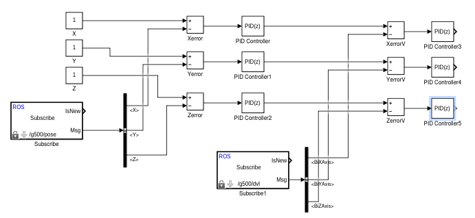
The purpose of this guide is not about creating a good controller but show how to communicate UWSim and Matlab-Simulink. In this tutorial we are going to create two cascaded controllers to move the vehicle, the first of them will read the position from the simulator and receive a target position producing a desired velocity. The second controller will read the UWSim vehicle velocity and the previously calculated velocity reference to send the thrusters effort to the simulator. As we will be controlling the vehicle in position (x,y,z) we will need 3 controllers, one for each axis.
Our setup is ready now, so we should start creating our simulink model to control the vehicle. Open Matlab-Simulink and open a new model (file -> new -> model).
Position controller
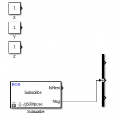
The first step is create the position controller, we need two inputs: reference and vehicle position. The reference position can be added as 3 constants (x,y,z), so we browse in the library for constant block and add 3 of it. It is recommended to change their name clicking on the letters below to (X,Y,Z) so they can be easily identified. The vehicle position must be read from sensors, we could use any kind of input for it as long as we have the absolute position. In this example we will use direct absolute position from the simulator in order to focus on the important part, Simulink-UWSim interaction.
So we will read the information from /g500/pose topic which is the position the dynamics is sending to UWSim. To do so look for subscribe in the library browser and add the Robotic System Toolbox subscribe block. As the topic already contains X,Y,Z information we only need one block of it. In order to configure it is recommended to keep the simulator running so we can directly choose the topic from a list, so launch the scene in UWSim. When the simulator is up and running double click the subscribe block, press select option and choose /g500/pose from the list. This will automatically configure the block to receive data from the selected topic.
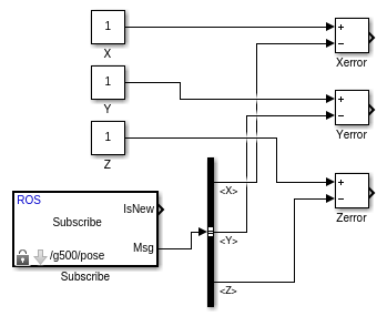
As the topic in subscriber block contains (X,Y,Z) data and more, we need a bus selector to split it. Add a bus selector and connect Msg output from the subscriber to its input. Double click on it to configure, if everything went as it should you will see in the left box signals in the bus (Position and orientation), select X,Y and Z from position and delete the default ones.
Before adding the controllers we need to obtain the error subtracting the vehicle position to the reference position, so add three subtract blocks and connect reference position (X,Y,Z) (constant blocks) to the + input of each block and the outputs of the bus selector to the - input of them. Once again each block should be renamed for readability to Xerror, Yerror and Zerror respectively.
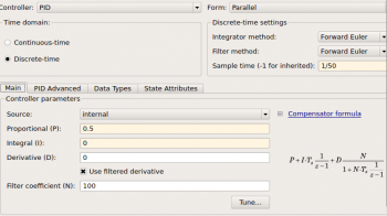
Finally add 3 PID controller blocks from the library and connect each one to the previously created subtract boxes. Double click each controller to configure it, change the following parameters: Mark discrete time, set Sample time to 1/50, Proportional (P) to 0.5 and Integral (I) to 0. As we mentioned before this tutorial is for showing the communication between Simulink and UWSim so we are not going to discuss the controller parameters which are clearly not the best.
At this point we already have the velocity reference, which is the speed at we want the vehicle to move, we can add some scopes and execute it to see everything is working, but as we are using the dynamics package we need to send thruster efforts to move the vehicle so we need the second controller, a velocity controller.
Velocity controller
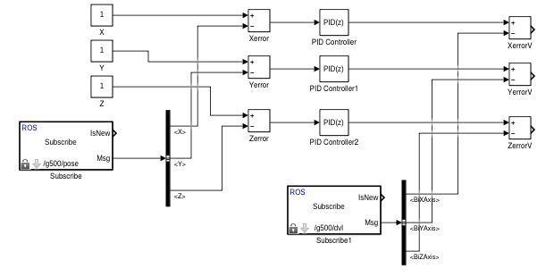
As we did before, we need reference and vehicle velocities, we already have the reference from the previous step so we need the vehicle velocity. So, we add a subscribe block and double click it to configure. In this case we have to choose /g500/DVL topic because the DVL simulated sensor is the one that contains the velocity at which the vehicle is moving. Remember, if UWSim is running we will be able to choose the topic and configure everything faster.
We repeat the process for the bus selector connecting it to the new subscribe block, but in this case we choose BiXAxis, BiYAxis and BiZAxis which are the measured velocities for each vehicle axis. Take into account this speeds are related to the DVL frame (vehicle), not to the world as the previous measure. It will work in this example because the vehicle is aligned with the world axis to make it easier, but if you want to use it in other environment you will need to transform this frame to the world (or the previous one to the vehicle frame and use vehicle-related coordinates). Or if the vehicle rotates the frames from the position and the velocities won't be aligned and the controller will never be able to reach a stable position (A transformation from local frame to world frame is needed).
So, the next step is adding three subtract blocks, one for each axis, and connect them to the position controllers outputs of the previous section and the measured velocities from the subscriber to obtain the velocity errors. As we did before, the reference is linked to the + input and the measure to the - port.
Now we need 3 PID controllers to produce the effort we want in each axis. Double click it and configure it appropiately, the following parameters are known to work: Mark discrete time, set Sample time to 1/100, Proportional (P) to 1 and Integral (I) to 0.
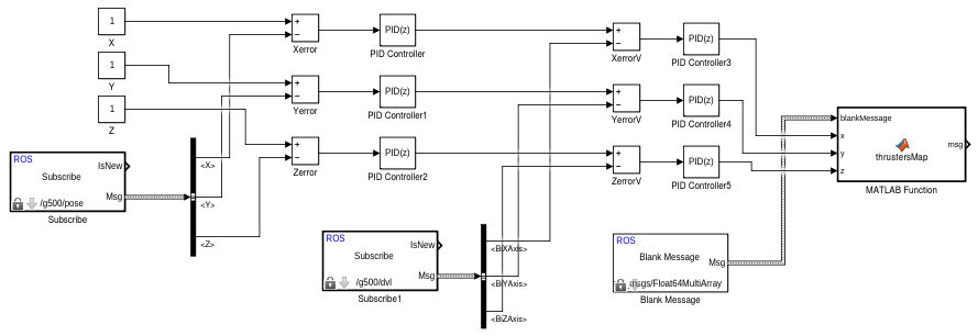
At this point we already calculated the necessary effort, for each axis, to control the vehicle while moving to a desired position. Now we need to map the axis effort to the vehicle thruster configuration, publish it in a ROS message and send it to the dynamics module.
Publishing the result
First of all we need a blank message to fill with our information, so search in the library for "Blank Message" block and add it to the model. Double click it to configure, select message type: "std_msgs/Float64MultiArray" which is the kind of message the dynamics module accepts for thrusters input.
This message is a list of efforts for each thruster the vehicle has. In our example, the Girona500 model has 5 thrusters: First two are for X axis movements (surge), the next two for Z axis(heave), and the last is for Y movement (sway). We can send efforts ranging from -1 to 1, the sign of the effort controls the direction of it. So mixing positive and negative efforts for each thruster in the same axis will produce a torque, girona500 can yaw and pitch using this, but we will not use it in this tutorial.
In order to fill the data in this kind of message we need a Matlab function as it is the only way (at least at the moment of writing this tutorial) to fill a nested array inside a ROS message. So we look for the "Matlab Function" block and add one. Double click to configure it, and you will be able to modify the text of a function. First of all we need to set the proper heading, as we need 4 inputs: the blank message and the desired effort in each axis, the output will be the filled message. So the first line should be like this:
function msg = thrustersMap(blankMessage,x,y,z)
When this is done try to run the model (some errors will appear, just ignore them), and the "Matlab Function" block should be updated with the correct amount of inputs/outputs. Now we have to set the data type of msg in the matlab function, so go back to the editor and click "Edit Data" in the list of the left you should see the 5 variables the function has, select "msg". Now select the type to "Bus: SL_Bus_MatlabTutorial_std_msgs_Float64MultiArray". Apply changes and go back to editing the function. This step tells Simulink the type of output our function has, so it can work with the rest of the model.
Assign the blank message to the msg output and fill the data with the appropiate mapping of your thrusters. Finally you will need to manually set the length of the array, so modify "msg.Data_SL_Info.CurrentLength" to do it. In this case we can do it as it follows:
% Assign the output message to be the same with input blank message
msg = blankMessage;

% Modify the nested message
msg.Data(1) = -y;
msg.Data(2) = -y;
msg.Data(3) = -z;
msg.Data(4) = -z;
msg.Data(5) = -x;

msg.Data_SL_Info.CurrentLength = uint32(5);
As can be seen some axis have been changed to make the axis of the vehicle match the axis of the sensors/world, we are not dealing with rotation issues in this tutorial. Now back to simulink model link the PID outputs and the blank message to the corresponding inputs of the new "Matlab function" block.
The only thing left to do is create a ROS publisher to publish the result in the ROS network and see our result in the simulator. So look for the block "Publish" in the robotic toolbox block, add one and connect the output of the function we just created to it. Double click it to configure, if we have UWSim running we can choose it from a list so we recommend to open it. Press select and choose "/g500/thrusters_input" from the list.
Finally you can change the simulation stop time (the small text box just in the top of the model) to a higher value (default is 10.0) to run the model for a longer time.
Now everything should be working, to test it: run UWSim, and run the simulink model, you should see the vehicle moving around the desired position. You can also change the target position in the constant boxes we added at the beginning and see how the vehicle moves to new position.
